How to Reduce Scrap in High-Volume Closed-Die Forging
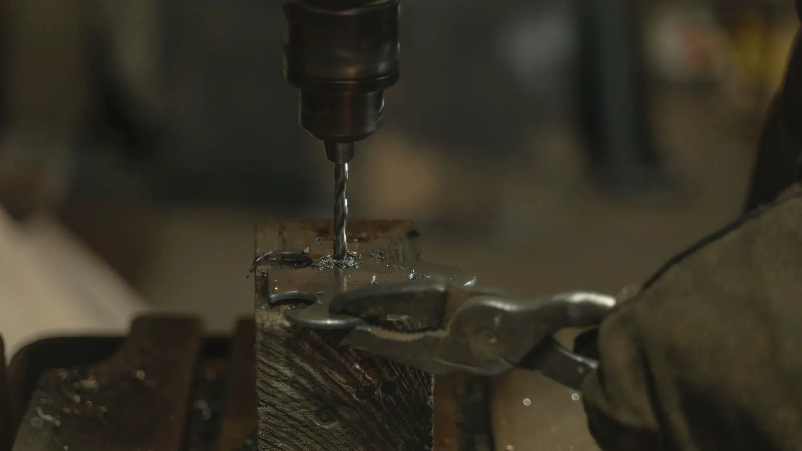
High-volume closed-die forging scrap usually traces to die wear, feed inconsistencies, or unstable heat. Reduce defects by stabilizing the hot metal, tightening die tolerances, and verifying every stage of the forming cycle with measurable checks.
- Scrap in closed-die forging often stems from inconsistent heat, die wear, or unstable feed.
- Tighten tolerances on die alignment, billet temperature, and lubrication to cut flash and defects.
- Use process optimization checks at every stage of the forming cycle.
- Verify final parts with dimensional and surface checks before release.
Why Scrap Accumulates in Closed-Die Production
Closed-die forging runs at high speed and high pressure. When one variable drifts, the defect appears immediately in the next few seconds. A slightly cool billet, a worn die face, or a feed that sits too far forward can all create flash, cracks, or dimensional failure.
The goal of forging scrap reduction is not to eliminate every defect. It is to keep the defect rate low enough that the line runs predictably. That means controlling the material, the die, the heat, and the measurement loop.
What You Need Before You Change Anything
Before adjusting the press or the die, confirm the baseline.
- Pull the last three production logs and identify the top three defect types.
- Check the die condition. Measure face wear, side clearance, and any visible scoring.
- Confirm the heat source is stable. Record the temperature at the billet and at the die entry point.
- Verify the feed position and the lubricant flow rate.
- Confirm the press force and stroke are within the approved window.
These prerequisites matter because a wrong adjustment can make a good process worse. If you change the die clearance while the heat is unstable, you will not know which change caused the new defect.
Step 1: Stabilize the Billet Temperature
The first failure point in many runs is heat. A billet that is too cool will not flow cleanly. It will leave flash, thin sections, or incomplete fill. A billet that is too hot can create oxidation, surface cracks, or die wear.
Set the temperature window based on the alloy and the die material. For most production runs, the target is a narrow band around the optimal forging temperature. Use a calibrated infrared sensor or a contact probe at the point where the billet enters the die.
Reason: The metal must be within the plastic range. If the heat is inconsistent, the die sees inconsistent flow, and the defect rate rises.
Check the sensor daily. A sensor that reads two degrees high or low can throw the whole process off.
Step 2: Tighten Die Alignment and Clearance
Closed-die forging depends on the die cavity filling completely without forcing the metal into an unwanted path. If the die is misaligned, the metal migrates to the path of least resistance. That creates flash, burrs, or incomplete sections.
Inspect the die alignment at least twice per shift. Check the gap between the upper and lower die halves. Measure the clearance at the parting line and at the draw length. Record the values in a simple log.
Reason: A small gap, even a fraction of a millimeter, can allow flash to escape where it should not. Over time, that gap widens, and the defect rate climbs.
If the gap is out of tolerance, stop the line. Do not try to compensate with more press force. More force creates more flash, not less.
Step 3: Control the Feed Position
The billet must enter the die at the same point every cycle. If the feed is too far forward, the metal starts to flow before the die closes. If it is too far back, the die closes around a cold section, and the metal does not fill the cavity.
Set the feed position based on the billet length and the die entry depth. Use a mechanical stop or a sensor to confirm the position. Check it after any change in billet size or alloy.
Reason: Feed position controls where the plastic deformation begins. A consistent entry point means a consistent deformation path.
If the feed drifts, the defect pattern changes. Look for flash on one side of the part. That is a sign the metal started flowing from the wrong point.
Step 4: Manage Lubrication and Die Coating
Lubrication is not just about preventing sticking. It controls the friction between the metal and the die. Too little lubricant causes galling and increased flash. Too much causes the metal to flow too freely and escape the cavity.
Check the lubricant concentration and the flow rate at the die entry point. Confirm the coating on the die face is even. A thin, even layer works better than a thick, patchy one.
Reason: Friction determines how the metal moves. If the friction is uneven, the deformation is uneven.
If you see scoring on the die face, clean it and re-coat. Do not run the die with a scored face. A scored face creates a channel, and the metal follows that channel every cycle.
Step 5: Monitor Press Force and Stroke
The press force and stroke must match the die design. If the force is too high, the metal is forced into the flash line. If it is too low, the die does not close fully and the part is incomplete.
Record the force at the peak of the stroke. Compare it to the approved value. Check the stroke depth as well. A stroke that is even a small amount short can leave the die open at the end of the cycle.
Reason: The die cavity is designed for a specific force. Exceeding that force creates stress in the die and in the part.
If the force is out of range, check the hydraulic pressure, the accumulator, and the valve settings. Do not run the press until the force is stable.
Step 6: Use In-Process Inspection
In-process inspection catches defects before they become scrap. A simple check at the mid-process stage can save a whole batch of parts.
Place a gauge or a sensor at a critical point in the die. For a closed-die part, that point is often the draw length or the final section. Check the dimension every few dozen cycles.
Reason: By the time the part leaves the die, it is too late to fix a small defect. Catching the drift earlier gives you time to adjust the process.
If the dimension drifts, stop the line. Adjust the feed, the heat, or the die clearance. Do not keep running and hope the defect goes away.
Step 7: Run a Final Verification Check
The final verification step is the last line of defense. Before releasing a batch, check a sample of parts against the drawing.
Measure the critical dimensions. Check the surface for cracks, inclusions, or oxidation. Verify the flash line. Confirm the part weight is within tolerance.
Reason: The process can be stable and still produce a few bad parts. A final check catches those parts before they move to the next operation.
If the final check fails, trace the defect back to the process. The cause is usually heat, die, or feed. Fix the cause, not just the symptom.
Common Mistakes That Increase Scrap
| Mistake | Effect | Fix |
|---|---|---|
| Running with a worn die | Flash, incomplete fill | Replace or re-machine the die |
| Inconsistent heat | Cracks, thin sections | Calibrate the sensor and stabilize the furnace |
| Feed drift | Flash on one side, incomplete part | Adjust the feed stop and verify the position |
| Excess lubricant | Metal escapes the cavity | Reduce the flow rate and check the coating |
| Ignoring in-process checks | Defects reach the final stage | Install a gauge at the critical dimension |
How to Verify the Process Is Holding
A process is holding when the defect rate stays low and the dimensions stay stable over time. Do not rely on a single good batch. Check the trend.
Plot the defect rate over several hours. If the line is flat, the process is stable. If the line is drifting, something is changing. Check the heat, the die, and the feed.
A stable process does not need constant adjustment. It needs consistent checks.
Final Verification
The final verification step is the release decision. Before releasing the batch, confirm the last three checks.
- The in-process dimension is within tolerance.
- The final sample passes the drawing.
- The defect rate is below the approved threshold.
If all three checks pass, release the batch. If any check fails, hold the batch and trace the cause.
The goal is not a perfect part. The goal is a predictable process. A predictable process gives you a low defect rate, a stable output, and a lower cost per good part.
Frequently asked questions
What is the most common cause of flash in closed-die forging?
Flash is usually caused by die wear, excess press force, or a billet that is too hot. Check the die clearance and the heat first.
Can I reduce scrap by just increasing the press force?
No. More force creates more flash and more stress in the die. Fix the cause of the defect before changing the force.
How often should I check the die clearance?
At least twice per shift and after any change in billet size or alloy. A small gap can cause a high defect rate.
What is the best way to catch a drift early?
Use an in-process check at a critical dimension. A gauge or sensor at the draw length can catch a drift before the part leaves the die.
How do I know if the process is stable?
Plot the defect rate over several hours. A flat line means the process is stable. A drifting line means something is changing.