Troubleshooting Low Toughness in Forged Crane Components
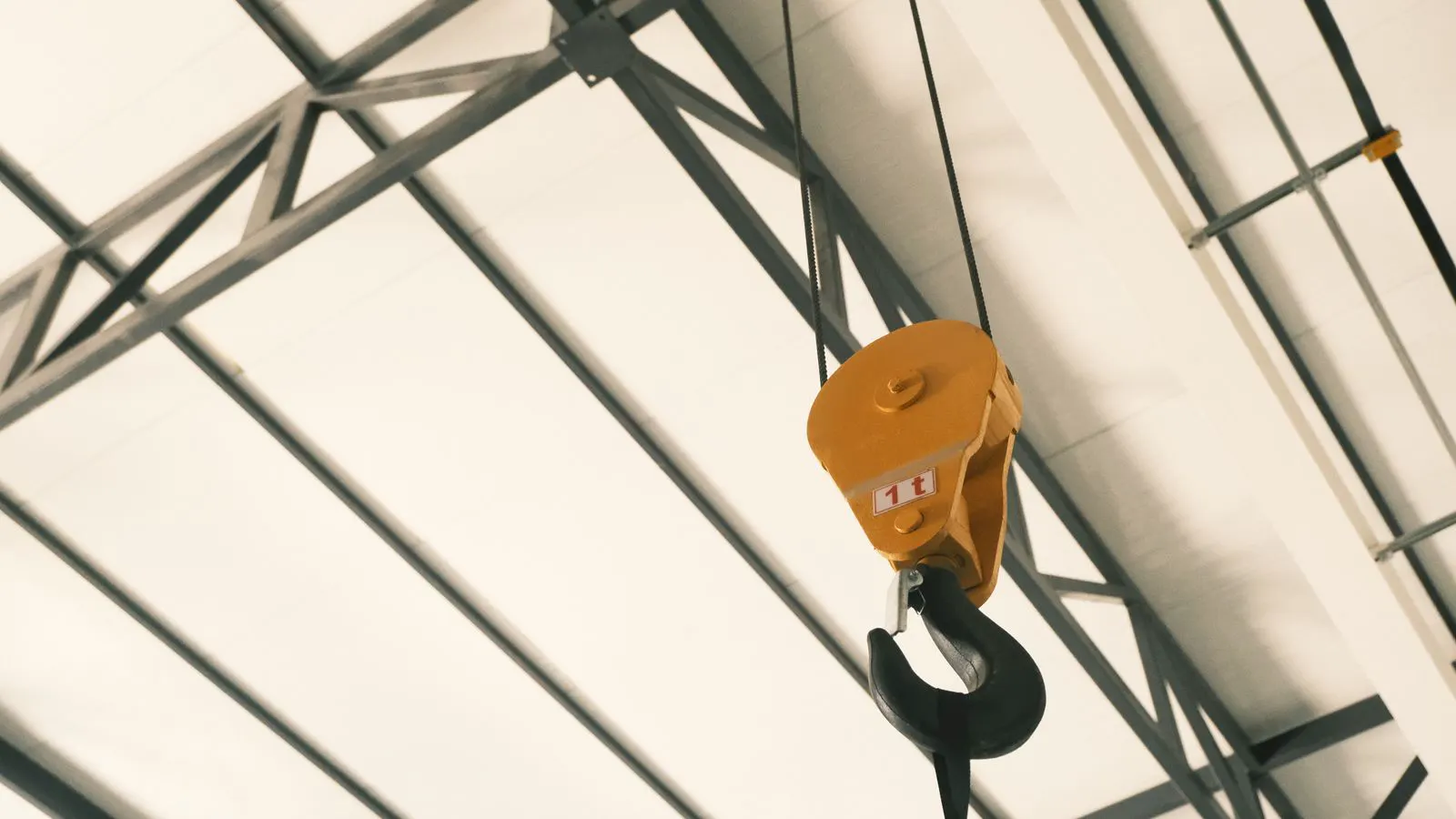
Low toughness in forged crane parts usually stems from improper heat treatment, material inclusions, or forging defects. This guide lists common symptoms, likely causes, and corrective actions to restore component reliability and meet performance requirements.
- Low toughness often indicates a failure in the heat treatment cycle or the presence of internal inclusions.
- Visual inspection alone is not enough. Destructive testing and material certification verification are required for accurate diagnosis.
- Corrective actions include reprocessing affected lots, adjusting furnace parameters, and improving raw material traceability.
- Documented quality control checkpoints at the forging and heat treatment stages prevent recurring issues in heavy equipment applications.
Identifying the Symptoms of Low Toughness
A cracked hook or a fatigue failure in a crane main hook assembly often points to a material problem rather than a design flaw. When forged crane components show low toughness in testing or field service, the failure is rarely accidental. It usually traces back to a specific process error in raw material selection, forging, or heat treatment.
Before applying a fix, the failure mode must be clearly defined. A part that is “weak” can fail for several distinct reasons. The physical evidence left on the component helps narrow down the cause. Engineers and procurement managers need a systematic way to isolate the root cause. The following sections break down the most common symptoms, their likely origins, and the practical steps to resolve them.
Common symptoms include:
- Brittle fracture. The break surface is flat and granular, with little deformation. This suggests the material lacked ductility. In a field failure, a brittle hook often snaps cleanly with no warning deformation. The flat surface indicates the metal did not have the energy to stretch before breaking.
- Fatigue cracks. Cracks appear at stress concentration points, such as the root of a hook throat or a weld joint. The metal may show a bright, shiny area near the fracture origin. This shiny zone is the beach mark left by the crack growth. It usually starts from a small surface defect or an internal inclusion.
- Surface pitting or etching. The surface may show pits or a dull, oxidized finish that does not match the surrounding area. This often indicates corrosion or surface contamination that occurred during storage or handling. It can also be a sign of improper quenching media that attacked the surface.
- Unusual hardness readings. Specific zones on the part may be significantly harder or softer than the specification. A hardness map of the failed part can reveal if the issue is uniform or localized. Localized hardness spikes often point to heat treatment errors or residual stress concentrations.
Identifying these traits on a sample part or a failed component is the first step. It guides the testing strategy and helps determine if the issue is uniform or localized.
Troubleshooting Low Toughness in Forged Crane Components
The table below maps common symptoms to their likely causes and the required corrective actions. This matrix serves as a quick reference for quality teams reviewing test reports or inspecting rejected parts.
| Symptom | Likely cause | What to do |
|---|---|---|
| Flat, granular fracture surface | Under-tempered steel or improper quenching | Review heat treatment logs. Check furnace temperature uniformity. Retest affected lot. |
| Internal porosity or voids | Gas inclusions or poor die design | Perform ultrasonic testing. Inspect forging dies for wear. Verify raw material gas content. |
| Localized soft zones | Incomplete austenitizing or cold working | Check heating cycle parameters. Verify material pre-conditioning. Consider re-forging. |
| Surface cracks after machining | Residual stresses or thermal shock | Implement stress relieving. Adjust cooling rates. Inspect tooling for vibration. |
| Inconsistent hardness across part | Uneven heat distribution in furnace | Calibrate thermocouples. Improve furnace loading patterns. Validate with multiple test coupons. |
Material Certification and Traceability
One of the most common sources of low toughness is a mismatch between the material supplied and the material used. For heavy equipment, such as crane hooks, the base steel must meet specific impact energy requirements. If the supplier delivers the wrong grade, or if the heat number is mislabeled, the part will fail in the field.
Buyers must verify material certificates against the heat number stamped on the forging. The chemical composition and mechanical properties must align with the drawing and specification. Discrepancies in carbon, manganese, or alloying elements can significantly alter toughness. A higher carbon content, for instance, will increase hardness but reduce impact toughness. A lower manganese content can affect the hardenability of the steel, leading to inconsistent heat treatment results.
A practical check is to request a mill test report for the specific heat used. If the forging supplier cannot provide this documentation, the material should be rejected. Without proof of origin, the component’s integrity is compromised. The mill test report should list the furnace heat number, the chemical analysis, and the mechanical test results from the bar stock before forging.
In a supply chain environment, heat numbers can get mixed up during inventory management. If a supplier stores multiple grades of steel in the same rack, a labeling error can lead to a catastrophic failure. The heat number is the link between the raw material and the finished part. It allows engineers to trace the problem back to the specific furnace run and the specific steel mill.
Forging Process Defects
The forging process itself can introduce defects that compromise toughness. These defects often form during the initial upsetting or die forming stages. Forged parts rely on grain flow to align the metallic structure in the direction of the load. If the forging process is incorrect, this alignment is lost, and the part becomes weak.
Inclusions and Slag
Internal inclusions, such as slag or oxide pockets, act as stress concentrators. They reduce the effective cross-sectional area and create weak points. These are often invisible to the naked eye but can be detected using ultrasonic testing. Slag inclusions usually come from the steel mill’s casting process. If the steel is not properly degassed, these pockets remain in the bar. During forging, the heat and pressure compress the metal, but the inclusions remain as voids.
Cold Shrinkage
If the metal is not held at the proper temperature during forging, it can cool too quickly. This leads to cold shrinkage, where the metal contracts unevenly. The result can be internal voids or micro-cracks that compromise the grain structure. This often happens when the forging die is not preheated or when the furnace temperature drops during the strike. The metal cools on the outside first, while the inside remains hot. As the outside cools and shrinks, it traps the hot core, creating internal stress and potential voids.
Die Wear
Worn forging dies can trap material in unwanted places or create uneven pressure. This leads to poor grain flow and can result in parts that are difficult to machine or that have weak grain boundaries. Dies are typically made of tool steel or graphite. Over time, the die cavity erodes. This changes the shape of the part and the way the metal flows. If the die is not maintained, the part may have a thin section that is prone to cracking, or a thick section that cools too slowly and forms undesirable grain structures.
Heat Treatment Errors
Heat treatment is where most toughness issues originate for high-strength forged crane components. The transformation from austenite to martensite, followed by tempering, dictates the final mechanical properties. This process is sensitive to temperature, time, and cooling rates. A small deviation can change the microstructure from a tough, impact-resistant state to a brittle, hard state.
Insufficient Tempering
If the tempering cycle is too short or the temperature is too low, the martensite remains overly hard and brittle. This makes the part susceptible to impact and fatigue failure. The fix is to extend the tempering time or increase the temperature within the specified limits. Tempering relieves the internal stresses created by quenching and converts the brittle martensite into a tougher tempered martensite. If the tempering temperature is too low, the stress relief is incomplete, and the part remains prone to shattering under shock loads.
Uneven Heating
If the furnace does not heat the entire part uniformly, some sections will transform at different times. This creates a complex internal stress state. The result is localized hardness variations and reduced overall toughness. Regular furnace calibration and proper loading practices are required to prevent this. In a batch furnace, the placement of the parts matters. Parts on the outer edge of the load may heat faster than those in the center. This creates a gradient of hardness across the part. A hardness map will show this gradient.
Quenching Issues
The quenching medium must be of the correct temperature and agitation level. If the quench is too slow, the steel may not fully transform. If it is too fast, it can cause distortion or cracking. Monitoring the quench tank temperature and flow rates is critical. The quench rate determines the microstructure. Too fast, and you get a brittle martensite structure with high residual stress. Too slow, and you may get pearlite or bainite, which are softer and less strong. The correct quench rate is a balance between strength and toughness.
Preventing Recurring Issues
Once a low toughness event is identified, the goal is to prevent it from happening again. This requires a shift from reactive testing to proactive process control.
- Standardize Heat Treatment Procedures. Develop a strict operating window for heating and quenching. Use automated controls where possible to minimize operator error. The operating window should define the exact temperature ranges and times for each stage of the cycle. Deviations should trigger an alarm or a hold on the process.
- Implement First Article Inspection. Verify that the first part of each batch meets all mechanical requirements before releasing the rest of the lot. If the first part fails, the entire batch should be held. This prevents the shipment of a defective lot. First article inspection includes dimensional checks, hardness testing, and impact testing.
- Monitor Raw Material Quality. Work with suppliers to ensure consistent chemistry and cleanliness. Request impact test results from the mill for critical applications. The raw material is the foundation of the part. If the steel is inconsistent, no amount of forging or heat treatment can fix it.
- Conduct Periodic Audit Checks. Randomly select finished parts for destructive testing. Compare results against the specification to verify process stability over time. This catches drift in the process before it leads to a field failure. Audit checks should be scheduled regularly, such as quarterly or per lot, depending on the criticality of the part.
When to Seek Third-Party Testing
If the root cause remains unclear after internal review, independent testing is necessary. A third-party laboratory can perform advanced analyses, such as metallographic examination of the fracture surface. This can reveal the sequence of crack initiation and propagation.
Third-party testing also provides an unbiased perspective on whether the component meets industry standards for heavy lifting equipment. This is particularly important when dealing with liability or insurance claims related to crane failures. A third-party lab can provide a report that is admissible in legal proceedings. The report should include the methods used, the results, and the conclusions. It should be free from bias and based on recognized standards.
Final Thoughts on Component Reliability
Low toughness in forged crane components is a serious reliability risk. It leads to unexpected failures and significant downtime. By systematically diagnosing symptoms, verifying material certification, and controlling the forging and heat treatment processes, manufacturers can ensure their parts perform as expected.
The focus must remain on data. Every test result, heat number, and furnace log must be tracked and retained. This documentation not only helps in troubleshooting but also builds a track record of quality that supports long-term supply chain reliability.
Frequently asked questions
How can I tell if a forged crane hook has low toughness?
Look for a flat, granular fracture surface if the part has failed. If the part is still in service, check for unusual hardness variations or surface pitting. Formal impact testing is the definitive method.
Does the type of steel matter for crane hook toughness?
Yes. The alloy composition and carbon content determine the base toughness of the material. For heavy equipment, specific low-carbon or alloy steels are often used to balance strength and impact resistance.
Can a part be reworked if it fails a toughness test?
It depends on the severity of the defect. Surface issues might be corrected with machining or stress relieving. Internal defects or bulk material issues usually require re-forging or re-heat treatment.
How often should I test forged crane components?
Testing should be done per lot or per heat, depending on the criticality of the part. Periodic destructive testing of finished components is recommended to verify ongoing process stability.
What is the difference between hardness and toughness?
Hardness measures resistance to deformation, while toughness measures the ability to absorb energy before fracturing. A part can be very hard but low in toughness, making it brittle and prone to sudden failure.