How to Specify Tolerances for Forged Metal Components
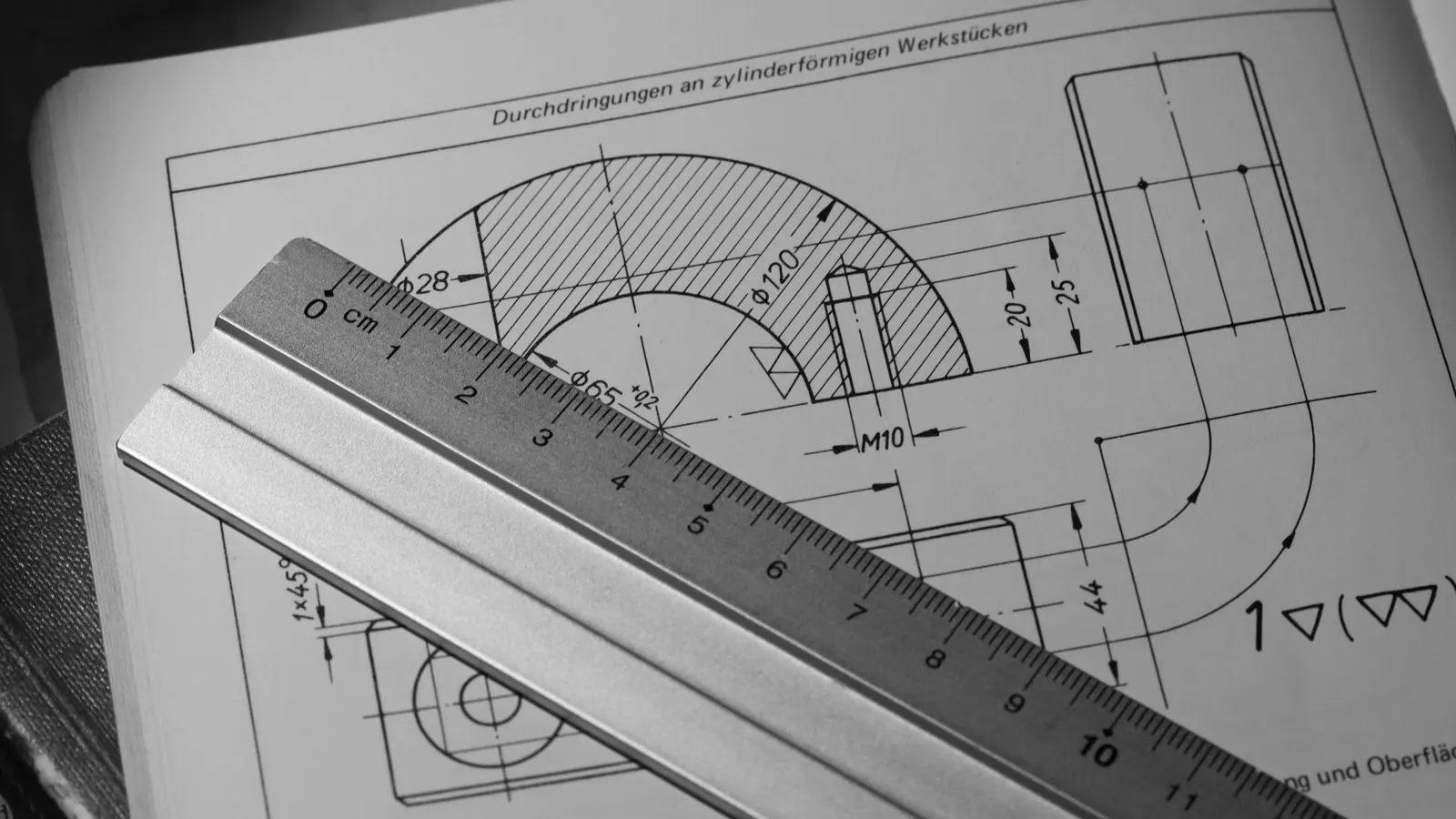
Specify tolerances by starting with functional requirements, selecting material and process, defining dimensional and geometric limits, and setting verification methods. This guide outlines the steps to create clear engineering drawings for forged metal components.
- Define functional requirements before setting dimensional limits to avoid over-machining.
- Use GD&T for geometric features and standard tolerances for dimensions.
- Specify material and process to ensure the forged metal components meet mechanical needs.
- Include verification methods and material certificates to confirm final part quality.
Start With the Function, Not the Drawing
Forged metal components are shaped to handle load, motion, or pressure. The tolerance you choose must protect that function. If a bearing seat sits on a shaft, the bearing fit determines the tolerance. If a gear mesh operates with a specific backlash, the tooth profile and pitch determine the limit.
Start by listing every functional requirement. This list becomes the basis for the drawing. A component that only needs to bolt to a housing requires less precision than one that seals against a rotating shaft. Over-specifying dimensions wastes money. Under-specifying causes fit-up failures in the field.
Before assigning numbers, review the assembly. How does the part move relative to its neighbors? What loads does it take? What environment does it see? The answers to these questions set the baseline for every dimension you will specify.
Match the Tolerance to the Material and Process
The material and forging process set the practical limits of what you can hold. Hot forged carbon steel behaves differently from a titanium alloy. A close-tolerance dimension on a soft, ductile material is easier to hold than the same dimension on a hard, brittle alloy.
Open die forging produces a part with a rougher surface and looser geometry. Press forging holds closer form. If you specify a tight tolerance on a dimension that the forging process cannot reliably hold, you are asking for heavy machining. Heavy machining removes material that the forging process already shaped. That increases cost and lead time.
Select the process that fits the tolerance. If a dimension is critical for strength, use a process that holds form well. If a dimension is only used for assembly, let the forging process handle the bulk and machine only the mating faces. This balance keeps the cost of the forged metal components in line with their actual function.
Define Dimensional Tolerances With a Clear Standard
Dimensional tolerances set the maximum and minimum size of a feature. A shaft with a tolerance of plus or minus 0.1 mm can be 10.1 mm or 9.9 mm. A flat face with a tolerance of 0.05 mm must stay within that band.
Use a recognized standard for the tolerance class. The standard tells the shop how to interpret the numbers. If you write a tolerance without a standard, the shop may guess. A guess leads to a rework or a rejection.
For most forged metal components, the tolerance class should match the feature function. A critical shaft might use a tight fit class. A non-critical web might use a loose general tolerance. Do not apply the same tight tolerance to every dimension. Apply the tight tolerance only where the function demands it.
Use Geometric Dimensioning and Tolerancing for Shape and Position
Dimensional tolerance controls size. Geometric tolerance controls shape and position. A shaft can be the correct diameter and still be bent. A flat face can be the correct thickness and still be twisted. A hole can be the correct size and still be out of position relative to another hole.
Use geometric callouts to control the features that affect function. A flatness callout controls the face that mates against a housing. A concentricity callout controls the relationship between a shaft and a gear. A perpendicularity callout controls the angle of a flange to a body.
Geometric tolerances are often tighter than dimensional tolerances. A shaft might be held to a loose diameter but a tight straightness. This is common. The function of a shaft is to turn without binding. A tight diameter with a bent shaft will bind. A loose diameter with a straight shaft will work.
The table below shows typical tolerance classes for common features in forged metal components. Use this as a starting point for your first pass. Adjust based on the specific function of the part.
| Feature Type | Typical Tolerance Class | Reason |
|---|---|---|
| Critical shaft | Tight fit class | Bearing or seal fit |
| Mating face | Medium flatness | Assembly and sealing |
| Hole position | Medium positional | Bolt alignment |
| Web thickness | Loose general | Structural support |
| Gear tooth | Tight profile and pitch | Meshing and noise |
Specify Surface Finish and Roughness
Surface finish affects friction, wear, sealing, and corrosion. A machined face that mates with a bearing needs a smooth finish. A face that bolts to a plate can be rougher.
Specify the surface finish in the drawing. The finish value is a number with a unit, such as microns or inches per foot. The finish applies to the specific surface you name. Do not apply a finish to the whole part. A forged part has a rough, textured surface from the forging process. Machining smooths selected areas.
A rough surface holds less lubricant. A smooth surface reduces friction. A sealed surface needs a finish that allows the seal to compress without tearing. A welded surface needs a finish that allows the welder to see the joint. Match the finish to the surface function.
Set the Verification Method and Material Certificate
A tolerance is only as good as the method used to check it. A caliper checks a single dimension. A coordinate measuring machine checks complex geometry. A bore gauge checks a hole. A dial indicator checks runout.
State the verification method in the drawing or the purchase order. If the method is not stated, the shop will use whatever is available. That may not be the method that gives the truest result. A bore gauge on a deep hole gives a different result than a CMM. A dial indicator on a rotating shaft gives a different result than a straightedge.
Also require a material certificate. The certificate proves the material meets the chemical and mechanical spec. A forged part made from the wrong steel will fail, no matter how tight the tolerance is. The certificate is a document. It is not a tolerance. But it is part of the specification that makes the part safe to use.
Final Verification Step
Before releasing the drawing for production, run a final check. Read the drawing top to bottom. Does every dimension have a tolerance? Does every geometric feature have a callout? Does every surface have a finish? Does the drawing name the verification method? Does the purchase order require a material certificate?
Take the drawing to a second engineer. Ask them to read it without the context. If they have to guess, the drawing is not finished. A clear drawing removes guesswork. A clear drawing reduces cost. A clear drawing protects the function of the forged metal components in the field.
Common Mistakes
Specifying a tolerance without a functional reason is the most common error. The engineer draws a dimension and picks a number because it looks right. That number does not protect the function. The shop machines the part to the number. The part fits. The part works. But the cost is higher than it needs to be. The second error is applying a tight tolerance to every feature. The shop spends hours on a non-critical web because the drawing says 0.02 mm. The third error is forgetting the geometric callouts. The part is the right size but the wrong shape. The fourth error is not naming the verification method. The shop uses a cheap tool and passes a part that would fail with a good tool.
Each of these mistakes comes from the same root. The drawing was written to control the size of the part, not the function of the part. When you write the drawing to control the function, the tolerances fall into place. The cost falls into place. The quality falls into place.
Frequently asked questions
What tolerance class should I use for a non-critical face?
Use a loose general tolerance that matches the part size. The face only needs to mate against a housing or a plate. A loose tolerance keeps the cost low without affecting function.
How do I know if a geometric tolerance is needed?
Check the function. If the feature mates against another part, or if the part rotates, or if the part seals, a geometric tolerance is usually needed. A face that only holds a bolt does not need concentricity. A shaft that turns in a bearing does.
Can I use the same tolerance for every dimension on a drawing?
No. A single tolerance class for every dimension wastes money. The critical dimensions need tight tolerances. The non-critical dimensions need loose tolerances. Match each tolerance to the function of that specific feature.
What is the difference between a dimensional tolerance and a geometric tolerance?
A dimensional tolerance controls the size of a feature. A geometric tolerance controls the shape or position of a feature. A shaft can be the correct diameter and still be bent. A flat face can be the correct thickness and still be twisted.
Do I need to specify the surface finish for every face?
No. Specify the finish for the faces that affect function. A face that seals needs a finish. A face that bolts does not. A face that wears does. A face that is only for assembly does not. Match the finish to the surface function.