Explaining Metallographic Testing for Forged Parts
Metallographic testing for forging cuts and examines a sample to reveal grain structure, inclusions, and defects invisible to the eye. This microstructure analysis confirms material properties and helps buyers verify that a forging meets the required mechanical specifications before acceptance.
- Metallographic testing reveals the internal grain structure and defects that external inspection cannot see.
- Microstructure analysis validates that the forging process created the required material properties.
- Buyers should specify sampling frequency and acceptance criteria in their purchase orders.
- A single micrographic sample can reveal issues that affect the entire heat lot.
Metallographic testing for forging is a destructive inspection method that examines the internal structure of a metal part. It involves cutting a sample, mounting it in epoxy, grinding and polishing the surface, and then viewing the cross-section under a microscope. This process exposes the grain structure, inclusions, and internal defects that determine how the part will behave under load.
What metallographic testing actually reveals
The primary output of a metallographic examination is a high-resolution image of the material’s internal architecture. Engineers look at several specific features during this review. The first is grain size, which describes the dimensions of the individual crystalline regions within the metal. The second is grain orientation, which shows how those crystals are aligned after the forging process. The third is the presence of inclusions, which are non-metallic particles trapped inside the material during melting or casting.
These features are not just academic details. They directly influence the mechanical properties of the final component. A fine, uniform grain structure generally produces a part with higher strength and better fatigue resistance. A coarse grain structure may indicate that the heating or cooling rates were outside the optimal window, potentially reducing toughness. Inclusions can act as stress concentration points, leading to crack initiation under cyclic loading.
How the sample preparation process works
The accuracy of the test depends entirely on how the sample is prepared. A typical procedure starts with cutting a small section from the forging using a diamond wire saw or a water-cooled abrasive cut. This method prevents heat buildup, which could alter the microstructure. The resulting sample is then mounted in a hard epoxy resin to secure it and protect the cut surface.
Next, the sample undergoes mechanical polishing. Technicians use a series of grinding wheels and finishing compounds with progressively finer abrasives to remove the surface layer and reveal the clean metal beneath. After polishing, the surface is etched. The etchant is a chemical solution that reacts with the metal grains to create visible boundaries. The choice of etchant depends on the material type. For example, ferritic and austenitic steels require different chemical compositions than aluminum alloys or titanium products.
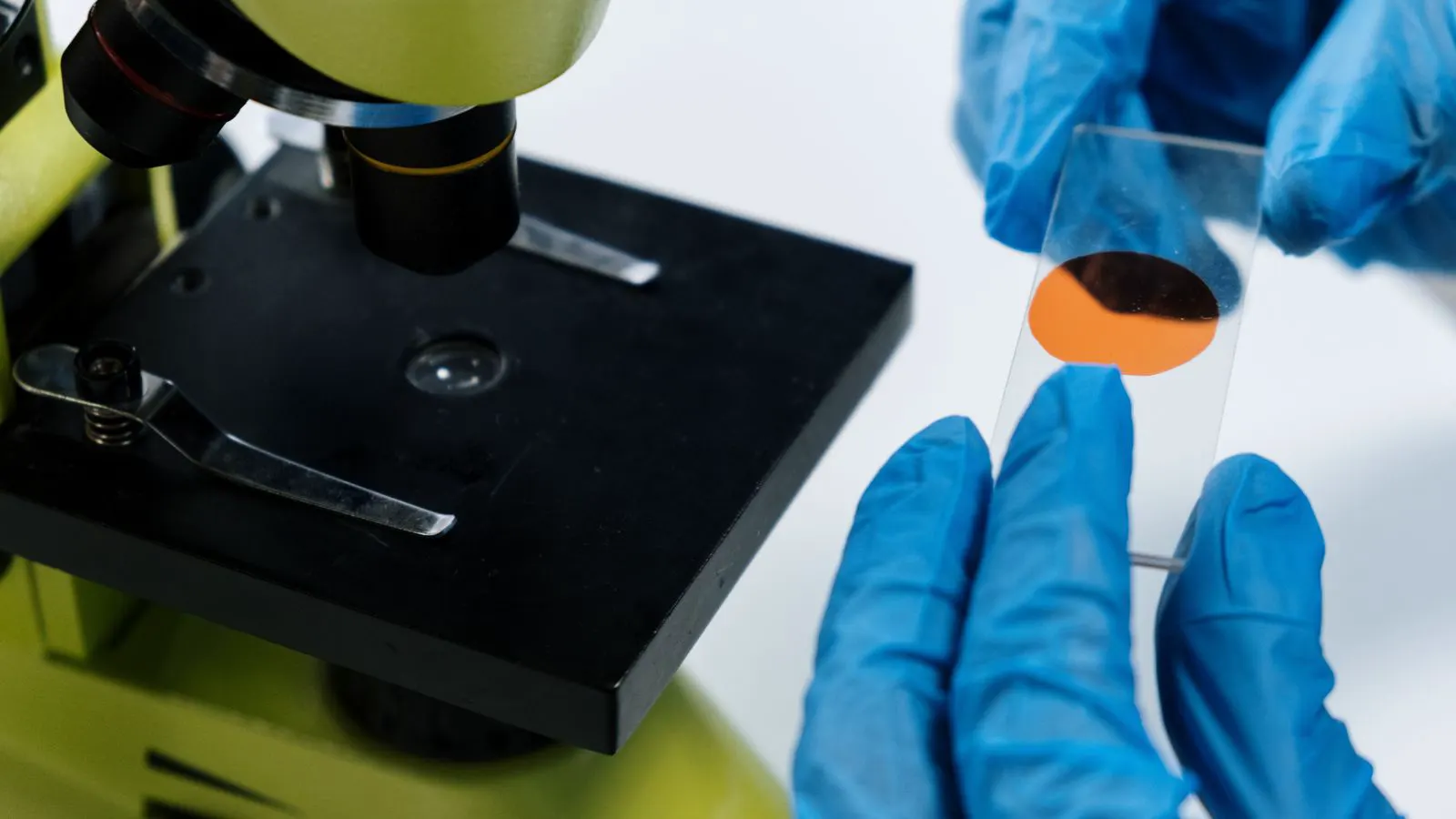
Once etched, the sample is placed under a light microscope or a scanning electron microscope. The resulting images allow the inspector to measure grain size, identify defects, and classify the material structure against the required specification.
Why grain structure matters for sourcing decisions
When evaluating a forging supplier, the grain structure is a key indicator of process control. Forging is a plastic deformation process that breaks up the original grain pattern of the starting billet or bar. A well-executed forging results in elongated grains that follow the contour of the die. This flow pattern helps distribute stress evenly throughout the component.
If the grain structure appears random or overly coarse, it suggests that the forging was not performed correctly. The part may have been heated too slowly, or the hammer blows may have been insufficient to properly refine the grain. In some cases, it indicates that the material was not heated to the correct temperature range for the specific alloy.
Buyers can use this information to verify that the supplier is following the correct thermal cycle. For example, if a specification requires a certain minimum number of forging blows or a specific die temperature, the resulting grain structure should reflect that process. Mismatched structures can be a red flag that the supplier is using a cheaper, less controlled process that may not meet long-term performance requirements.
Common defects found during microstructure analysis
Metallographic testing is one of the most effective ways to detect internal defects that other non-destructive testing methods might miss. While ultrasonic and radiographic methods are excellent for finding large voids or cracks, they often struggle with small, planar defects or inclusions that are only a few micrometers in size.
The most common defects identified during this inspection include:
- Hot tears: These are cracks that form during solidification when the metal is still hot and plastic. They often appear as dark, jagged lines in the micrograph.
- Hot shortness: This is a lack of ductility at high temperatures, often caused by impurities. It results in a brittle fracture surface that is visible under the microscope.
- Inclusions: Non-metallic particles such as sulfur, oxides, or silicates. These can be spherical, elongated, or clustered.
- Segregation: A non-uniform distribution of alloying elements within the grain structure. This can lead to localized areas of weakness.
- Decarburization: The loss of carbon from the surface of the steel during heating. This creates a soft layer that may not be visible to the naked eye but significantly affects the surface hardness.
Each of these defects has a different impact on the part’s performance. A small inclusion might be acceptable for a static load application but could be a rejection reason for a high-cycle fatigue component like a gear tooth or a turbine blade.
How to interpret the results for your application
Reading a metallographic report requires understanding the context of the part’s service conditions. A report will typically include photographs of the cross-section, a grain size measurement, and a description of any anomalies found. The inspector will compare these findings against the acceptance criteria defined in the purchase order or the applicable industry standard.
For high-strength applications, the grain size is often the most critical metric. A specification might require a minimum grain size to ensure that the part can withstand shock loading without fracturing. If the test reveals a grain size that is too coarse, the part may be rejected even if its tensile strength meets the requirement. This is because the impact of grain size on toughness and fatigue life is often more significant than its effect on static strength.
Buyers should also pay attention to the location of the defects. A small inclusion near the surface of a bearing race might be critical, while the same inclusion in the core of a large housing might be less problematic. The context of the defect’s location relative to the part’s stress concentration points determines its severity.
A practical example of a sourcing decision
Consider a manufacturer sourcing forged steel shafts for a heavy-duty industrial pump. The shafts must withstand continuous vibration and occasional shock loads. The supplier provides a batch of shafts that pass all dimensional checks and basic hardness tests. However, the buyer requests a metallographic test on a sample.
The micrograph reveals a slightly coarse grain structure and a cluster of small oxide inclusions near the surface. While the shafts are strong enough for static loading, the coarse grains and inclusions indicate a higher risk of fatigue failure over time. The buyer decides to reject the batch and returns the samples to the supplier. The supplier reviews the thermal cycle data and discovers that the preheat furnace was running two degrees too low, causing the steel to be less malleable during the forging stage.
By catching this issue at the sample stage, the buyer avoided a potential field failure. The supplier was able to adjust the furnace temperature and re-forge the remaining stock with the correct parameters. This example shows how metallographic testing serves as a quality gate that protects the end user from long-term performance issues.
How to specify metallographic testing in your purchase order
To ensure you get the right level of inspection, your purchase order must be specific. Simply stating “metallographic test” is not enough. You need to define the scope, frequency, and acceptance criteria.
| Specification Element | Description |
|---|---|
| Sample Frequency | Define how many parts per lot are to be cut and examined. |
| Sample Location | Specify where on the part the cut should be made to ensure the most critical area is tested. |
| Acceptance Criteria | State the maximum allowed grain size and the type of inclusions that are acceptable. |
| Reporting Format | Require the supplier to provide digital images and a narrative report. |
| Retention | Specify if the supplier must retain a sample for a certain period for reference. |
By including these details, you remove ambiguity. The supplier knows exactly what is expected, and the results are comparable across different lots and suppliers. This clarity is essential for maintaining a consistent quality level in your supply chain.
Frequently asked questions
How is metallographic testing different from ultrasonic testing?
Metallographic testing is destructive and examines the internal microstructure and small defects. Ultrasonic testing is non-destructive and detects larger internal voids or cracks without cutting the part.
Do I need metallographic testing for every forging?
Not necessarily. It depends on the criticality of the part. High-stress or safety-critical components usually require it, while low-stress parts may only need basic dimensional and hardness checks.
What is the most common reason for rejection in metallographic testing?
Inadequate grain refinement is the most frequent issue. This often results from incorrect heating temperatures or insufficient forging strikes during the production process.
Can I see the grain structure with a regular microscope?
No. A standard optical microscope is not sufficient. You need a light microscope with high magnification and a prepared, etched sample to reveal the grain boundaries clearly.
How does the sample preparation affect the results?
If the sample is heated too much during cutting or polishing, the microstructure can change, leading to inaccurate results. Proper technique is required to preserve the original condition of the forging.